Dimension > Angle, Line - Line (Annotate Menu)
|
|
Dimension > Angle, Line - Line (Annotate Menu) |
www.CAD6.com |
|
This command can be used to measure an angle shown by the position of two legs. It can be used to measure angles formed by existing objects.
Any line in an existing object can be identified as the first reference line (first leg). This can also be the edge of a rectangle or a leg of a circle segment.
Any line in an existing object can be identified as the second reference line (second leg). This can also be the edge of a rectangle or a leg of a circle segment.
The position of the ID point with reference to each leg determines which angle is measured.
After selecting the legs for the angle to be measured, the positions of the dimension line and the dimension text must be specified. To do this, several points have to be entered. How many, and which, points have to be entered, depends on the specified dimension parameters.
When choosing the Change Parameters (+ESC) command, the "Dimension With Line" dialog appears where this command's parameters can be specified.
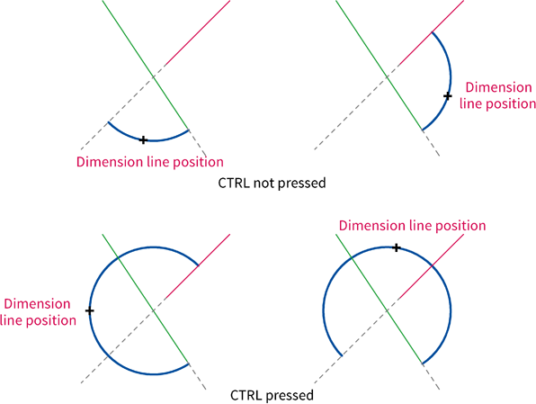
The position of the dimension line is determined by the position of a point through which it should run. If a particular distance has been entered, then the point determines the approximate position of the dimension line. This point can be entered using the mouse, by clicking anywhere in the drawing. The dimension line position must always be entered, even if the dimension line display is disabled, since it determines the angle to be measured.
If during dimension line position entry the CTRL key is pressed, the "large" angle (above 180°) will be measured. Else, the "small" angle (below 180°) will be measured (see graphic).
If "Center Dimension Text" or "Close Dimension Text" is not set:
The position of the dimension text can be entered using the mouse, by clicking anywhere in the drawing. The positioning of the dimension text can be restricted with the "Center Dimension Text" and "Close Dimension Text".
If "Rotate Dimension Text" is set:
The dimension text direction can be entered using the mouse, by clicking anywhere in the drawing. The location of this position relative to the dimension text position determines the dimension text's rotation angle.
After entering all the parameters, the measurement is made. If the "Tolerances" check box was enabled in the dimension parameters, then the "Dimension Number and Tolerances" dialog appears, in which the tolerances and supplementary dimension text can be specified. The "°" symbol is added after the dimension text.
The dimension is not automatically assigned to the current layer. Instead, the command Layers > Defaults is used to decide whether they should be assigned to the current layer, or another specified layer. The same goes for pens, which can be assigned using the command Pens > Defaults.
You can use Advanced Text Capabilities (consisting of Formatting, Attributes, Variables, Statements, Mathematical Terms) in all texts, dimensions, variables, and attributes!
A dimension contains two property sets - one for the dimension line, and one for the dimension text. For example, this makes it possible to show the dimension text in a different color to the dimension line or assign the dimension text to a different layer from the dimension line. If the command Modify > Object Properties > Edit is used on a dimension, you can switch between the two property sets by clicking the corresponding tab. This allows you to view and alter both property sets separately.
|
CAD6studio Release 2024.1 - Copyright 2024 Malz++Kassner® GmbH